Wooden sleepers beneath wooden rails. Nicolas Wood, Practical Treatise on Rail-Roads, 1825, Fig II
Stone blocks beneath Fishbelly rails. Nicolas Wood, Practical Treatise on Rail-Roads, 1825, Fig VII
Cast-iron plateway. Coll National Welsh Museum, 2013
Rough stone supports. East Carandon Farm, Cornwall, GB, 2010
Load pattern for cross-sleepers. E.Winkler, Der Eisenbahn-Oberbau, 1875, Fig 149
Steel sleeper with wooden blocks for rail mounting, PLM. Der Eisenbahn-Bau der Gegenwart, 1908, Abb 243
Steel longitudinal sleeper, Hohenegger 1894. Der Eisenbahn-Bau der Gegenwart, 1908, Abb 377
First sleeper of reinforced concrete, Monier, 1884. Von Emperger, Handbuch für Eisenbetonbau, 1912, Abb 13 - 16
Reinforced concrete sleeper War Department, WW2. Mid-Norfolk Railway, Dereham, GB, 2014

The forces that passing vehicles exert on the rails are caused by their weight, by acceleration and braking, and by wind picked up by the train. All of this has to be transferred to the embankment. This can be done by “simply laying the rails on the ground”, which also happens with a number of simple rail shapes, permitted by low weights and speeds of the trains, but it mainly happens by laying the rails on a support and attaching it to it. This support in turn rests in the ground and distributes the force over a larger surface, so that the pressure on the subsoil (usually the ballast bed) is smaller and thus also the subsidence in that subsoil. These supports have developed along with the technical development of the rails.

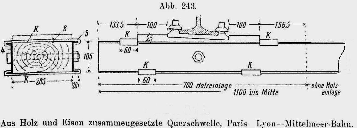
With the wooden rails, there were immediately cross timbers to keep the rails at the right distance. With pushed mine carts, these could still be planks, but sturdy beams the size of the rails or heavier, called sleepers, were soon used. In some cases, composite structures of beams and solid planks were used, but these were the exceptions. Timber lends itself well to fixing rails and rail chairs with wooden pegs, dog spikes and chair bolts.

Because the wood is preserved under vacuum and pressure with chemicals, the useful life as rail support can be up to several decades. Wood is therefore still used as a sleeper all over the world.

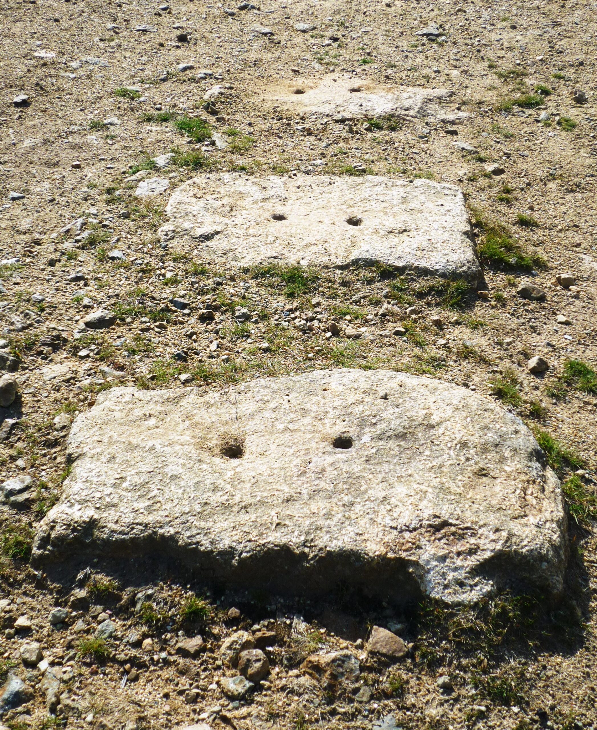
From the cast-iron rails (from 1791), some designs were laid on the ground, kept at distance by cast-iron cross-links with no bearing function, others came to rest with their ends or with cast-iron chairs on stone blocks, cut more or less precisely into a rectangular shape. Because these stone blocks were heavy and partially buried in the ground, they remained in place. There were also cast iron rails that came to rest directly or with chairs on wooden sleepers. The widely distributed local initiatives provided a multitude of solutions! Fixing the rails required at least one hole to be cut into the stone, into which usually a wooden plug was hammered to drive nails or turn chair bolts.

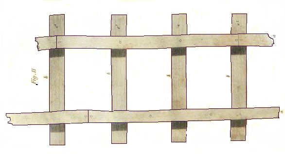
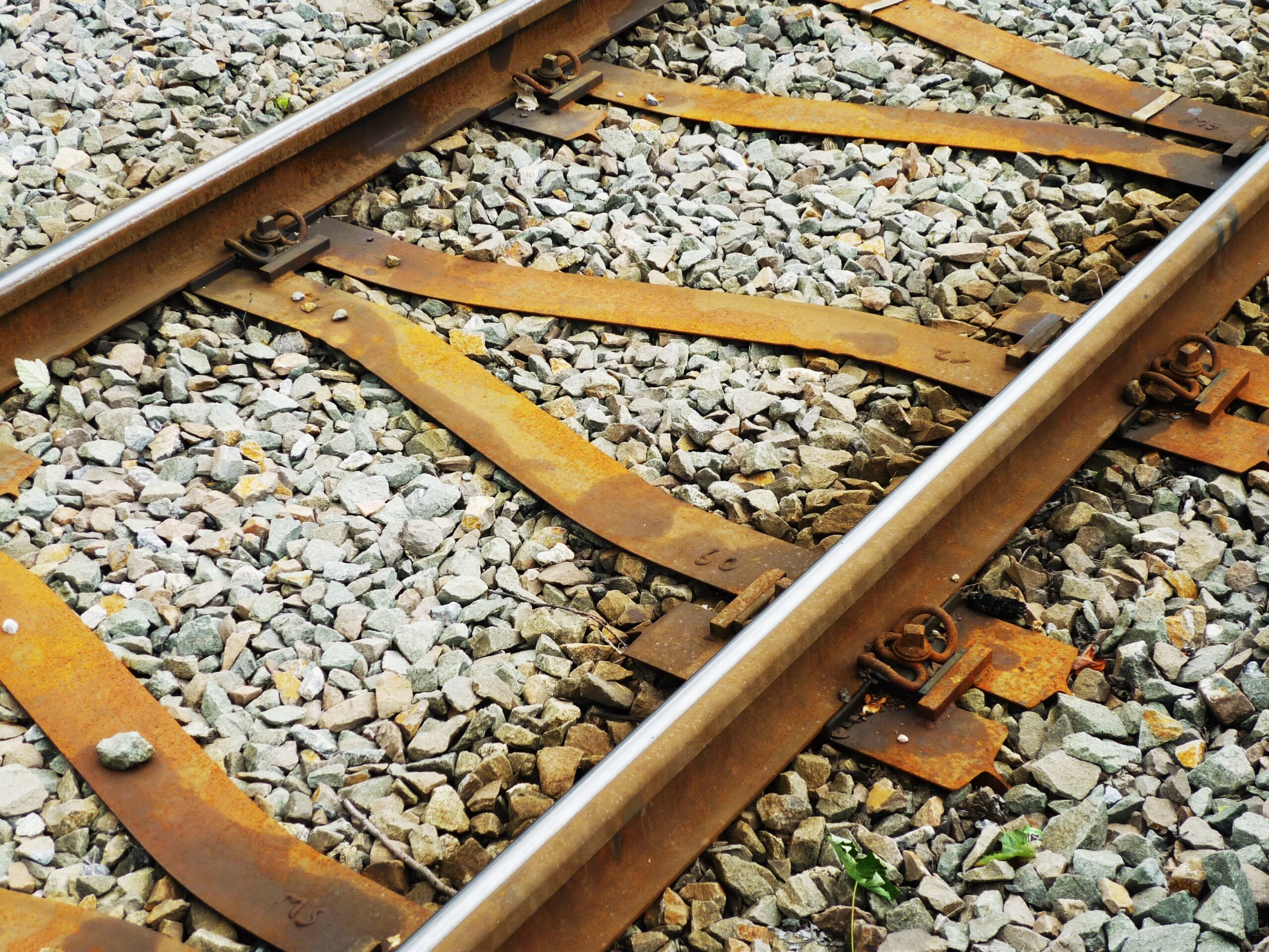
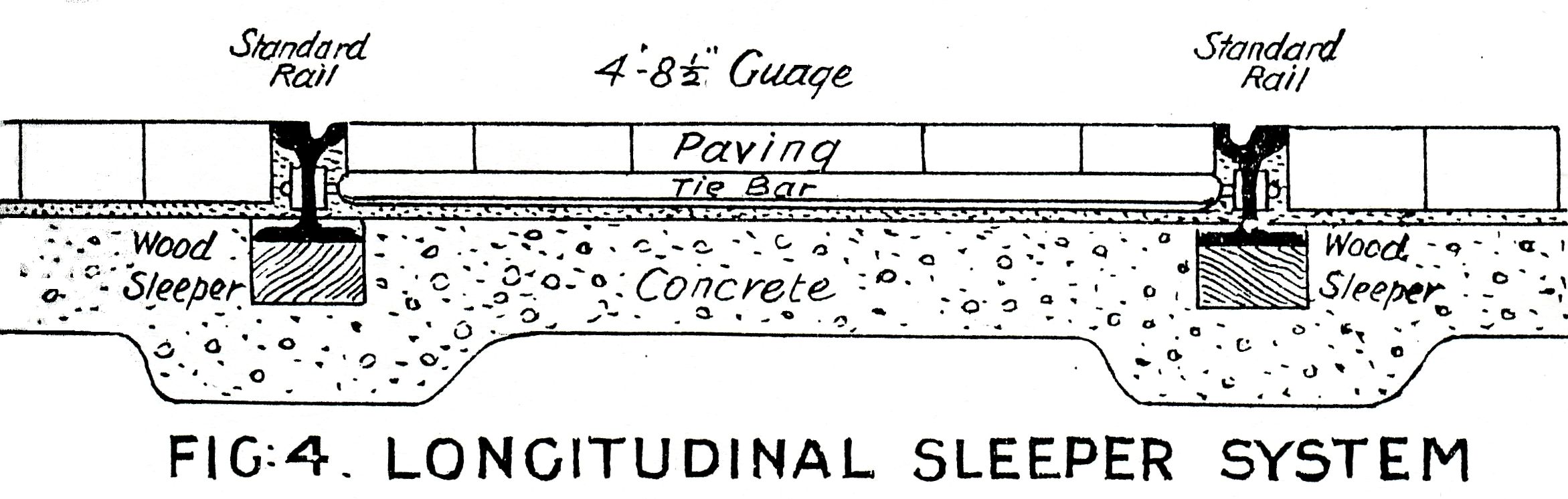
After the first iron rails were rolled in 1820, the previously mentioned supports were also used for this, but wooden longitudinal girders were added. They then needed spacers to ensure the track width, in the form of a metal rod or a wooden beam, at a much greater distance from each other than was usual for sleepers.

Stone sleepers were also tried in 1834, but this was far from a success. Not only did the susceptibility to fracture prove to be a problem, but the in time production of the large numbers that were required even for short railway lines was a major problem.

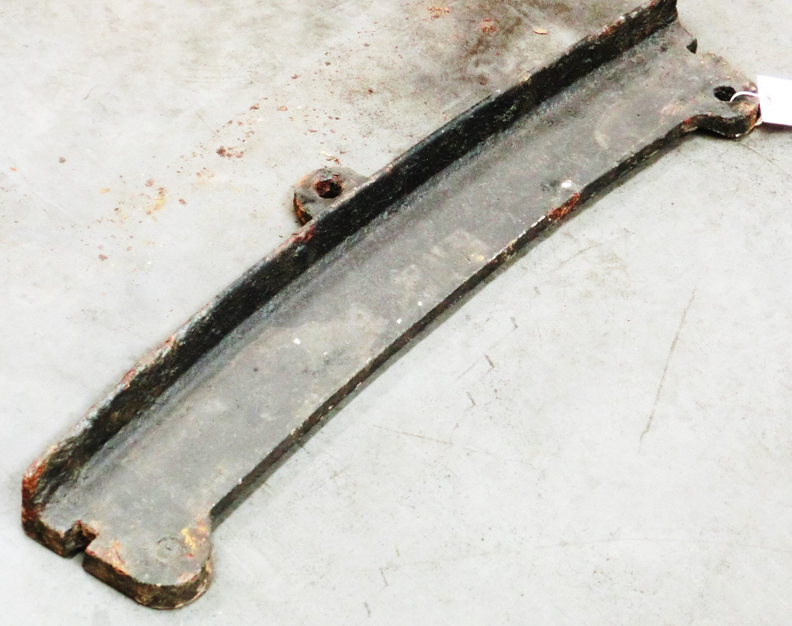
Of course, making wooden structures was not new in the 19th century, after all, that had been done for thousands of years, and so the decay of wood was also a very well-known problem. It should not surprise us that various techniques were developed around 1840 to stop or at least slow down the decay of wood. Even then, this was accompanied by the use of dangerous and environmentally harmful chemicals and it hardly helped. From 1846 onwards, therefore, other solutions were sought by making shells and plates of cast iron or iron sheets that would replace the wooden sleepers. Rails were usually attached to it with cast-on chairs and wooden or iron wedges. The success has been moderate, but they may still be found under little-used tracks in some countries.

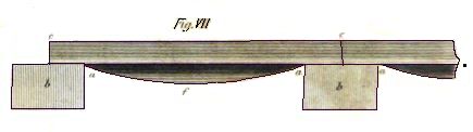
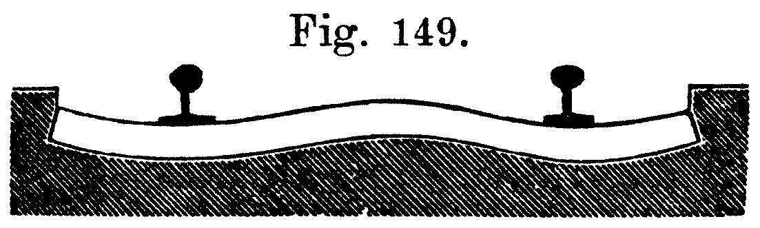
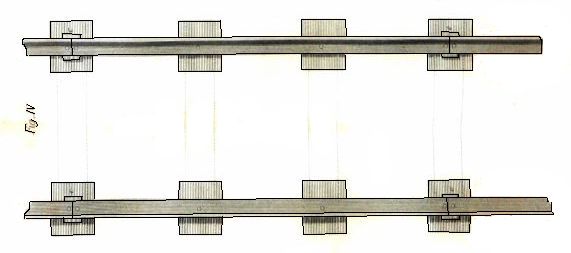
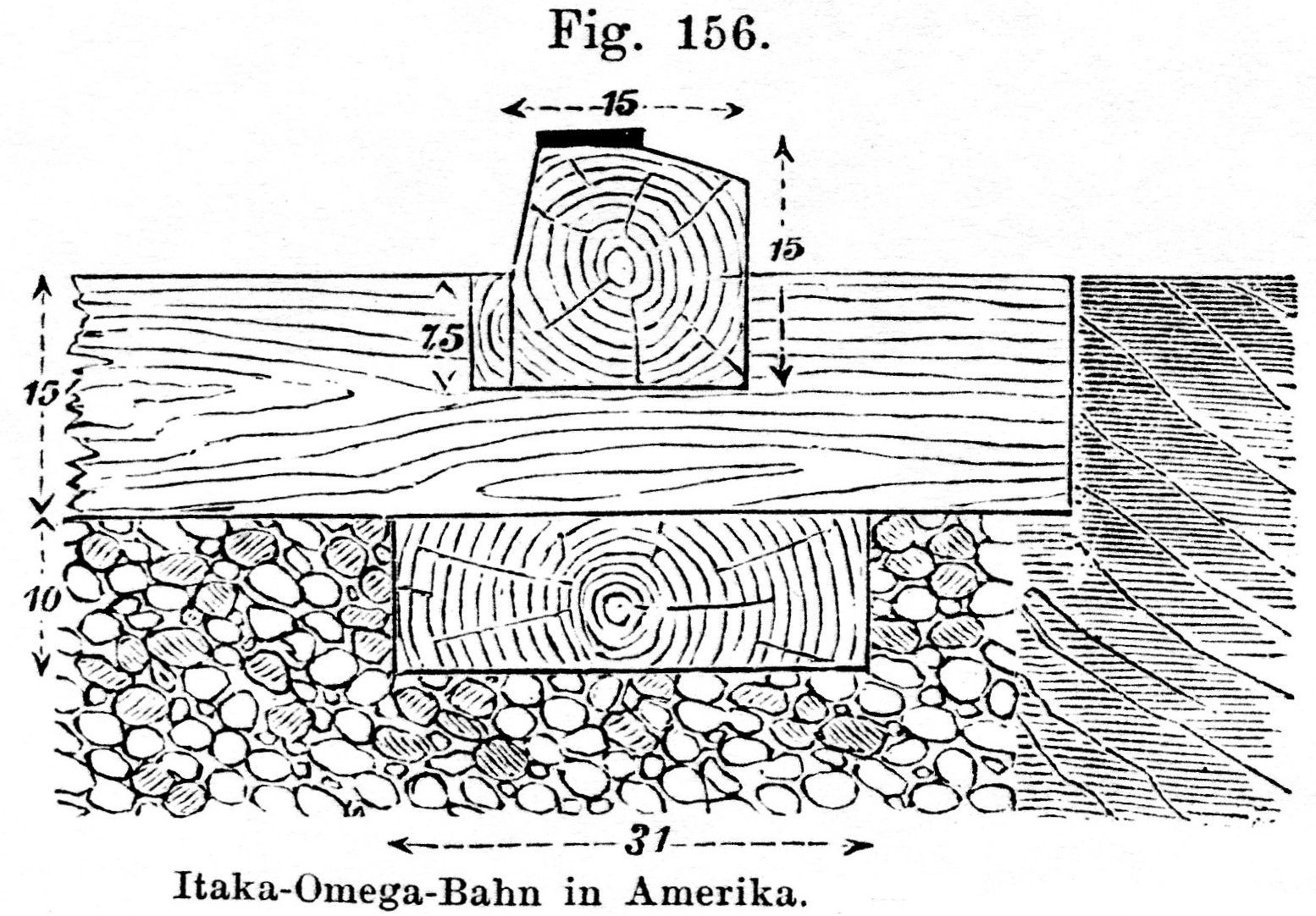
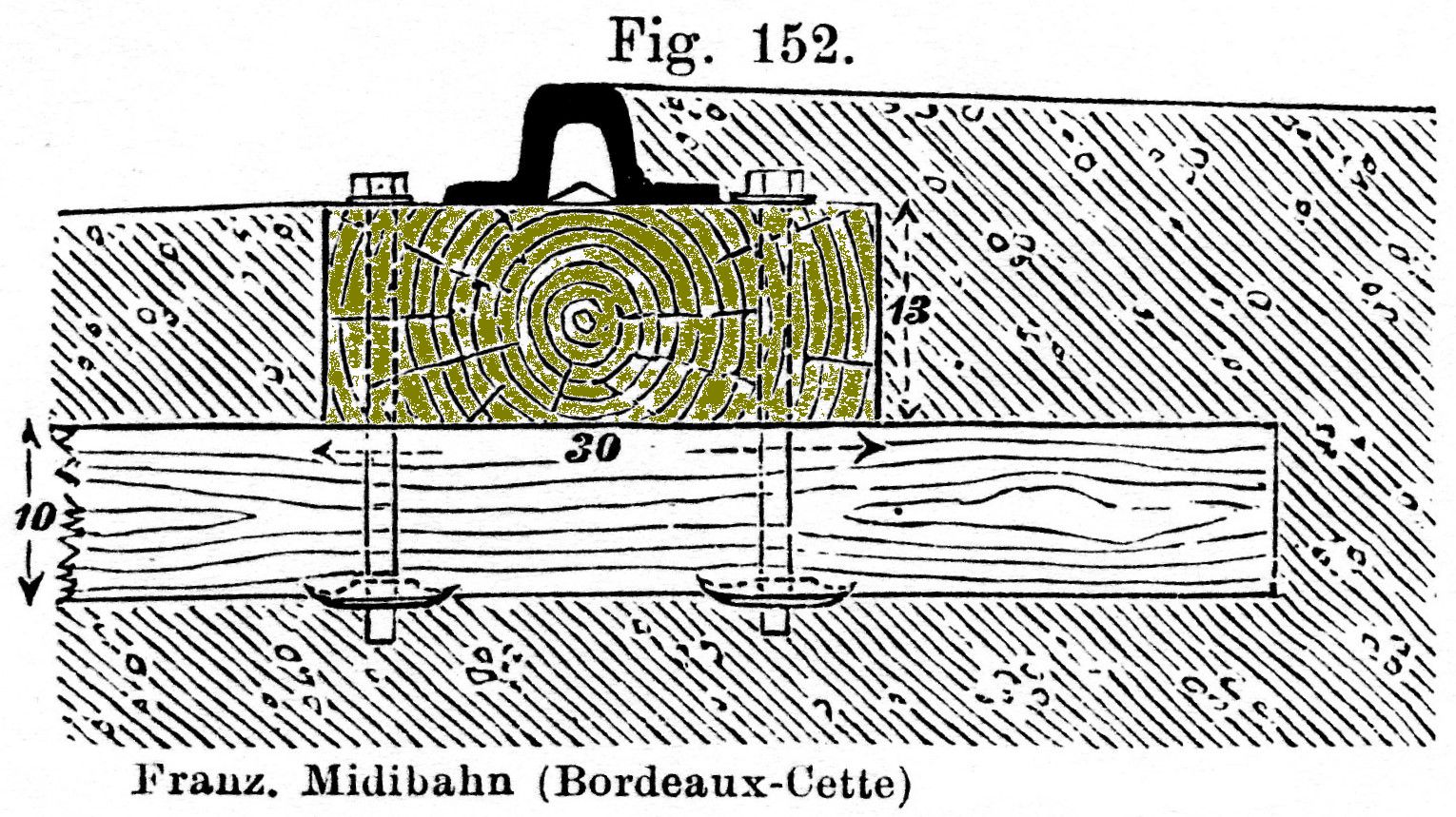
An interesting development was that attempts were made to make the sleepers in such a way that their properties were better adapted to the load pattern that occurs. The vertical forces are by far the greatest that have to be transferred to the ground and they press directly under the rails on the track bed. In the middle part no force can be transferred at all, because there is no rail there (rack rails are an exception to this, which we will not discuss). Because wooden sleepers are slightly flexible, that vertical force is transferred by two pieces of the sleeper to the roadbed. There is nothing to do for the middle part. In 1858 the idea arose not to lay timber there, but to couple two pieces of wooden sleeper under the two rails with a spacer. This idea has been reflected in countless later designs – also made of materials other than wood – and also realized. The rail fastenings were no different on the two-piece sleepers than on the one-piece versions.

A good answer to the limited lifespan of wooden sleepers had not yet been found, which led to the introduction of iron and steel sleepers in 1862, and a little later also of longitudinal sleepers of the same material. A drawback of the material was the high costs, especially for steel, which was therefore little used at that time. Another attempt was made in 1867 with “artificial stone”, blocks of cement or asphalt with a bit of wire reinforcement in it, but it did not work. The production technology was probably not developed far enough yet.

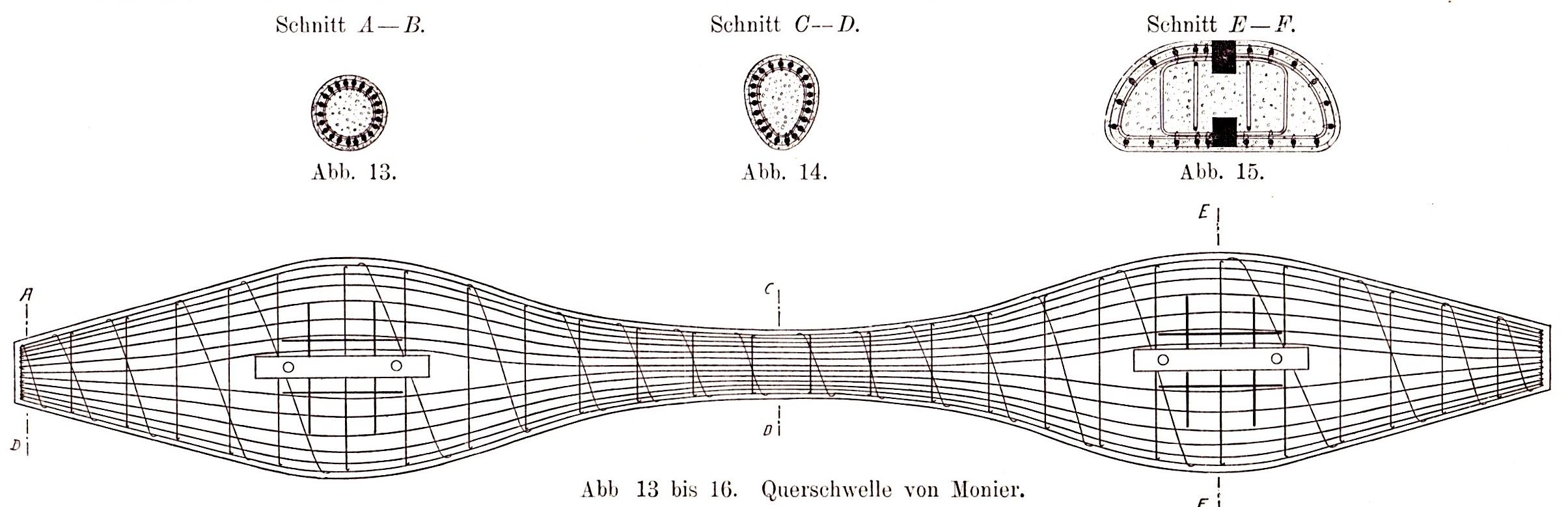
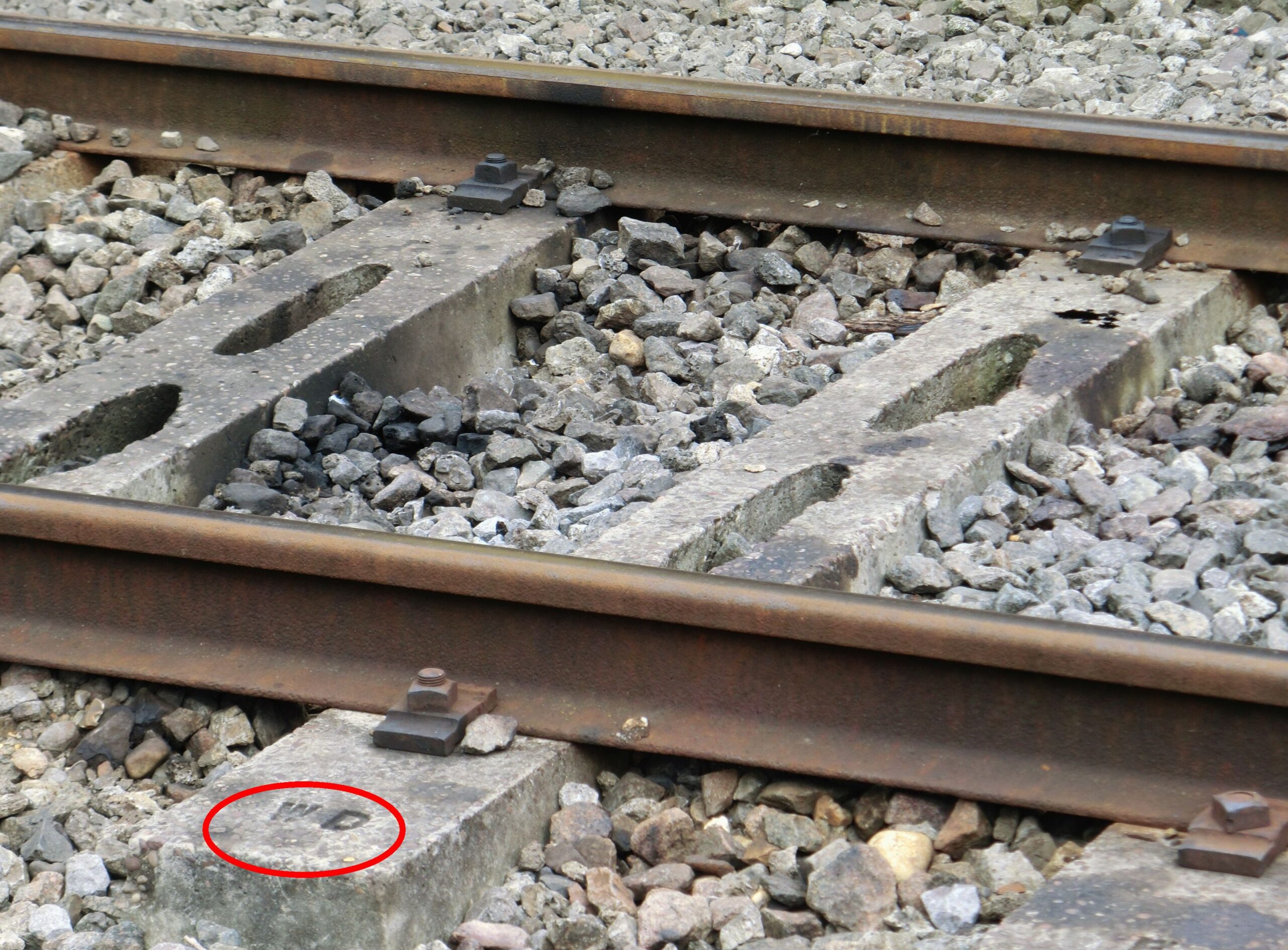
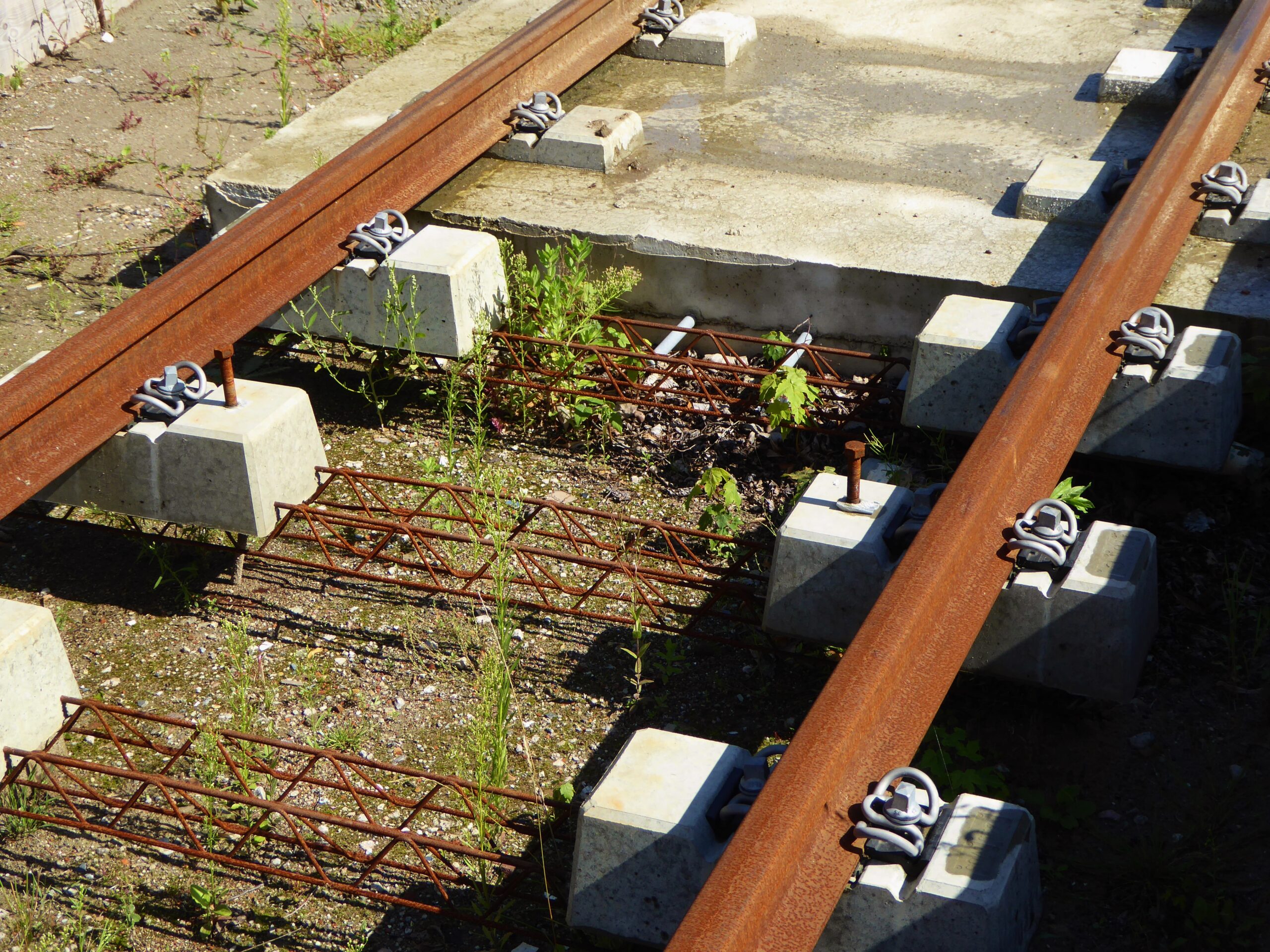
Even if today we have become accustomed to the use of concrete as a building material for railways, it is surprising to read that a timid attempt to use it was made as early as 1867, but the same happened as with artificial stone, the knowledge of materials was still far from far enough. And so were the concrete sleepers that were first made and laid in 1884, but which took until after World War II for the technology to reach the point where they could be used on a really large scale. One of the problems encountered was to give the concrete enough strength that the sleepers were resistant to bending. This did not work well with classic “weak” reinforcement. The concrete already had hairline cracks before the reinforcement could do its work when subjected to bending, allowing moisture to penetrate that could freeze in winter and cause the reinforcement to rust. The other problem was the fastening of the rails. 

Stone blocks beneath L-rails 3 yard long. Nicolas Wood, Practical Treatise on Rail-Roads, 1825, Fig IV
Compound wooden support for wooden rails. E.Winkler, Der Eisenbahn-Oberbau, 1875, Fig 156
Cast-iron distance keeper for plateway. Coll National Welsh Museum, 2013
Bridge rail on long timber with wooden distance keeper. E.Winkler, Der Eisenbahn-Oberbau, 1875, Fig 152
Heap of abandoned cast-iron shells. Ferrocarril del Sur, Miramar, Argentina, 1993
Wooden twin sleeper, Dutch State Railways 1882. A.Haarmann, Das Eisenbahn-Geleise, 1891, Fig 910
V2 Fig 165
‚Artificial stone‘ (asphalt) block , Stierlin, 1867. E.Winkler, Der Eisenbahn-Oberbau, 1875
Campbell’s concrete sleeper with timber blocks for rail mounting. According to Organ für die Fortschritte … 1908, p 434-435
Abandoned prestressed concrete sleeper, two stressing nuts visible, 2008. Serveis Ferroviaris de Mallorca, Enllac

There were no plastic dowels yet, so that invariably had to be done by pouring blocks of wood into the concrete or attaching them to the sleeper with extra parts. The rails were then fixed in that wood with the classic dog spikes and collar bolts. It is precisely this wood that decayed very quickly or became loose during drought. Nevertheless, there have been some designs that have had long-term success, such as the French Orion sleeper from 1924 on which the rail chairs were also attached with chair bolts in wooden blocks and which was still in use in the 1990s, and also a sleeper of the British army from the World War II on which the rails were fixed with through bolts, and which is still in use today.

The real solution only came when prestressed reinforcement was applied where the concrete in the cross beam is already pressed together before it has completely cured. This allows the sleeper to bend without causing hairline cracks. In the transition to resilient fastenings, their metal holders and also the plastic dowels for collar bolts immediately were cast in into the sleepers and then the real triumphal march for concrete sleepers began.

Large German steel manufacturers saw their market for sleepers completely lost and decided around 1980 on a counter-offensive. Steel sleepers were developed in a Y-model, which were connected with steel parts. These intermediate parts were integrated in a completely new way with the rail fastening. This form of support has become successful especially for winding mountain routes and is still in ample use. The system bears the German name “Y-Schwellen” and is used on a roadbed or on asphalt layers, which are then usually finished with ballast gravel.

The ‘streetcars’ (a means of transport between tram and light rail, which was quite heavily constructed) caused a furore in the United States in the early 20th century, but they were so heavy and the services so intensive that the track used at that time had a short life. The solution to this was found in 1912 by laying the track on reinforced concrete slabs and in many cases also pouring a concrete road surface for other traffic upon it. This method can be seen as a precursor to the current concrete slab track, which is called “Feste Fahrbahn” in German. From the 1960s onwards, a series of variants was developed especially for use on high-speed lines, in which whole or half sleepers are interwoven with asphalt layers and / or concrete slabs.

At the end of the 20th century, a number of rail profiles were developed especially for tramway tracks to be laid in grooves. With the Nikex track, these were recessed grooves in precast concrete slabs, with the LR55 track in precast concrete beams and with Eria swirl rail they were milled into an asphalt layer in order to save the curing time of concrete. With BBest track – intended for heavily loaded railways – two channels are left open when pouring a full concrete slab into which, after curing, two plastic channels are placed and aligned before being grouted in. Finally an elastic polymer channel /boot is inserted , into which the rail is pressed.

As the latest developments in rail supports we undoubtedly see the plastic sleepers that have been made from 1971 for very different reasons. One reason is to give recycled plastic a good use, another is to make a highly vibration-dampening sleeper from polyurethane foam that is reinforced with long glass fibers to give it bending strength. The latest development is the use of sulfur, which is released in large quantities from petroleum through desulphurization. The sulfur completely replaces cement and water in the concrete. It melts at ~ 120 ° C, is mixed with aggregate and some additives in the molten state and then solidifies in casting molds to a sufficiently hard and bending strong product. At the end of its useful life, this material can be remelted again at that much lower temperature for direct reuse.

We have seen that the lifespan of many track designs and materials used was generally so short that better solutions were sought. We have to take that “short” with a pinch of salt, because in many cases it turned out to be fifty years or more. In any case, far too long to immediately replace tracks with the latest inventions. There are also large differences in the intensity with which railway tracks are used and replacement is therefore not always urgent. The result is that at present almost all railway companies (or railway administrations) use many types of track side by side. And that brings its own charm.

two

Steel Y-Sleeper, Aha, Germany, 2014. Deutsche Bahn Netze
Ancient tramway track on through concrete layer. PWI Journal, 1909, FIG 4
Slab track, in front half twin sleepers not poured in yet, at the back fully embedded, 2017. BRU tramway line, Galgenwaard, Utrecht
RB GB BBeatty ERS 20140618 Longmarston (7)
Plastic gutters holding BBest rail embedded in concrete. Longmarston, GB, 2014