Rail fastenings

The function of rail fastenings is to keep rails firmly on their support. So sideways and in height displacement of the rails and tilting of the rails must be avoided as this can cause the train to derail. Longitudinal shifting of the rails (creep) can also lead to other problems such as breaking of welding bolts, damage to switches and crossings and track buckling. The latter is the jumping aside of entire sections of track, which, in addition to considerable damage, can also lead to serious derailments. For vibration damping, however, it is desirable to allow the possibility of slight movement.

The whole range of rail fastenings is so large that it is impossible to cover them all exhaustively in one long book, let alone on this website. We therefore limit ourselves to a global exploration of the development of rail fasteners.

Pegs and pins

Where the rails rest on their supports, we find the rail fastenings. In the beginning with the wooden rails on wooden sleepers, these were very simple wooden pegs. They fell out of use when the wooden rails were replaced with iron ones, but experienced a revival of which more later. The wooden pegs were followed by iron pegs and then by rail spikes with heads which were made in numerous adapted shapes to accommodate the rail base properly. The rails that were and still are attached with this, fill the entire range from the early wooden rails on various supports to modern steel rails, but the latter only on wooden supports. Rail spikes can still be found on a number of secondary lines and yards. Except that the heads show a great variety, there has also been a lot of tinkering with the stem of the spikes. When train wheels pass over a wooden sleeper, the wood is compressed a little each time and therefore a little destroyed. The spike then loses its pressing force on the rail foot and appears to have a tendency to rise slightly after the pass. This makes unwanted rail creep possible. That is why many ways have been devised – and some have also been put into practice – to combat this spike lifting. Ribs and barbs in all shapes and sizes!

Wooden peg with wooden rails, Tyneside (GB) 1807 M.J.T.Lewis, Early Wooden Railways, 1970
Iron peg for L-rail on wooden sleeper. John van Laun, Early Limestone Railways of South-East Wales, 1999
Range of rail spikes Collection DSM Harskamp (NL) 2010
Measures to keep rail spikes in the timber: barbs, torsion and 2x reduction. A.Haarmann, Das Eisenbahn-Geleise, 1891
Splitspike, making impossible to pull out A.Haarmann, Das Eisenbahn-Geleise, 1891

Dowels

The rail spikes could not just be driven into stone supports. First, a large hole was chiseled, a wooden plug was hammered in there and only then the rail spike. The wooden plug was developed into a mass product and refined in many ways. They were called “dowels” and could be provided with pre-drilled holes, outside ridges, saw cuts for proper splicing and even external threads. This was all because, after their initial application in natural stone rail supports, they also came into use to enable solid fastening of rail spikes in wooden sleepers of lesser quality. It also happened that holes had to be drilled in used (and thus partially worn and damaged) wooden sleepers. In these applications, therefore, much higher requirements were placed on the dowels than on the sleepers themselves. That was the reason for making them from very good wood, usually oak, and also treating them with creosote, which significantly extended their life. There was, of course, also a tendency among the railway companies to reduce costs, which is why cheaper and thus softer types of wood were also purchased for their sleepers. It happened that when such cheaper sleepers were purchased, hardwood dowels were immediately placed in them, sometimes with external threads so that the dowel itself was already perfectly fixed. In the tests with concrete sleepers around 1900, the decay of dowels in the concrete was almost inevitable, because the other options for attaching rails were with through bolts or with wooden blocks lying on them. That entailed quite a few drawbacks. When the production of prestressed concrete sleepers got underway in the 1950s, dowels were immediately poured into the concrete. Unfortunately, despite the preservation of wooden dowels, their useful life has remained rather limited and that was the reason to start using plastic as a raw material as soon as it became available.

It can be said that rail spikes and dowels are the rail fasteners that – albeit in very different versions – have been in use for the longest time without interruption.

Wooden dowel in stone support Merthyr-Tydfil (GB) 1800. Naar A.Haarmann, Das Eisenbahn-Geleise, 1891
Wooden dowel in woorden sleeper Organ für die Fortschritte des Eisenbahnwesens 1917
Wooden dowel in early concrete sleeper North Norfolk Railway (GB) 2014
Prestressed concrete sleeper with plastic dowel ÉI Portlaois (IRL), 2013

Chairs and keys

Nowadays we see almost exclusively flat-bottom rail that stays fine on the supports, but there were also rail profiles that needed a rail chair to remain in the correct position, which already started with the square iron rail of Nixon (1805). The T-shaped rail profiles that were rolled from 1820 and the somewhat later double-headed rail also needed chairs. They were almost always made of cast iron and generally had the same shape. In the beginning the chairs were fixed on the support with pegs and iron pins. If the supports were stone with a dowel, and in the case of wood without such. Later, fastening the seats with chair screws became common, although combinations of chair screws with iron pins were also common. The number of holes for the pins, spikes or chair screws varies from 2 through 3 to 4.

Keys were also an absolutely necessary attribute for the rail seats, as the rails had to be properly secured between the chair cheeks. It is striking how detailed the early iron keys for the T-rails were made, with very precisely milled keyways in the chair cheeks. Wooden keys were used for the double-headed rails, often with precisely defined and conformally executed angles that matched the rail and chair cheeks profile. Spring steel keys were used from the end of the 19th century and it may be noted that these wooden keys and the steel David key are currently still in use on the British railways (including the London Underground). This means that the chair-and-key system has also reached the very respectable age of 200 years!

We have yet to deal with the revival of the wooden peg. Contrary to popular belief, double-headed rails have been used in many European countries, including Germany. One of the last applications there was in a tunnel of the Wuchtalbahn, also called Sauschwänzlebahn (pigtail railway) because of the countless curves. In that tunnel, the DH rail was only replaced by a flat bottom rail in 2002. The humidity in the tunnel was so great that steel bolts and pins immediately after installation began to rust so strongly that the track was not reliable for long. Just because cast iron chairs are less likely to rust, that chair track has been kept in use there for so long. The creosotated oak pegs securing the chairs to the sleepers held up much better there than their steel fellow components.

T-rail in cast-iron chair with key London & Greenwich Railway (GB) 1838 A.Haarmann, Das Eisenbahn-Geleise, 1891
Cross-cut wooden key J.F.Boekholt, De Bovenbouw van Spoor- en Tramwegen, 1910

What follows below relates only to flat-foot rail, because the development of double-headed rail and its attachments has been almost completely covered by what has been described above.

Iron and steel sleepers

The iron and steel sleepers and all-metal superstructure from the second half of the 19th century brought with them separate specific fastenings that can only be used on this type of support. Often this is with hammerhead bolts that are inserted through a rectangular hole and then turned 90 °. The nuts then press on a clamping piece that presses on the rail foot. The shape of the clamping piece (or of special accessories) can be such that a lateral adjustment of the rail foot is possible. This is important to accommodate rails with different foot widths and also to enable track widening in curves.

Tee-bolt with clamp for steel sleeper Heusinger von Waldegg’s Musterconstructionen für Eisenbahnbau, 1878

Chair screws

Chair screws were given another very important field of application. They were also – and still are very widely – used to secure flat bottom rails. The collar head then presses on the edge of the rail foot. They hardly work loose, which was precisely the problem with the rail spikes. They still come in handy in wooden sleepers and also with modern elastic Nabla and Vossloh fastenings in concrete. They have become an almost universally used attachment.

When the rail spikes or chair screws hold the rails without the help of other parts, it is called direct fastening. An example is the “Est track”, of French origin.

Directe railfastening with chair screw, ‘track Est’. The rail is resting on a poplar pad. After Artur Fürst, Die Welt auf Schienen, 1918

Base plates

We have already seen above that wooden sleepers are slightly compressed by the passing wheels and the wood fibres are damaged. With increasing load (force and frequency) that compression and the associated problems also increase. To limit the impression of the wood, base plates were therefore introduced. The pressure between the rail and the support plate is not critical, but the pressure between the support plate and the sleeper decreases due to the larger surface area of ​​the plate. Often these base plates are held in place by the rail spikes or chair screws that hold the rails. Especially with larger base plates, the plates themselves can also be fixed with rail spikes and / or screws, whereby the spikes and / or screws holding the rail protrude through the plates. That is called a mixed rail mounting.

The first indirect fastenings were created in the 1850s, whereby the fastening of the base plate on the support is completely separate from the fastening of the rails on that plate. Indirect fastening in particular has known an incredible number of different designs. These three types of attachment (direct, mixed, and indirect) are all abundant. With all three there are also versions in which the base plates are provided with ribs between which the rail is placed. In this way a more stable track is made, and a greater freedom is also obtained in order to give the clamping of the rail a specific shape.

An extremely well-received indirect fastening has become known under the name K-fastening, which came into use from 1925. Regardless of which mount is used as a rule for a railway line, the K-fastening is almost always used for the switches and crossings in that line. It is also a very popular attachment for certain line sections.

Direct railfastening, rail spikes with base plate SdB Grovane (N), 2019
Indirect railfastening by Hohenegger, 1887 SZDC Libun (CZ) 2019

Resilient fastenings

As early as the fourth quarter of the 19th century, superstructure technicians were concerned with the loss of pressure due to compressed wood and the wear of rail spikes and chair screws. From that time onwards, numerous designs have been made for rail fastenings with resilient components that provide a permanent pressure on the rail foot. These could be metal springs in all kinds of shapes, but also natural rubber as an inlay in rail seats and special constructions. The primitive elastic spikes did not last, but the necessity remained. Only the resilient rail spike developed by the German Rüping in 1934 turned out to have a future. The American Max Bernuth, who had become rich with the trade in creosote for the preservation of wooden sleepers, saw perspective in this and set up factories in the Anglo-Saxon language area under the name of the Elastic Rail Spike Company, which even before 1940 produced and applied Rüping’s design worldwide.

This success was followed and countless inventors also contributed, some with great success. Here are a few that did not build on existing fastening components, but came up with completely new concepts, such as Arthur Dean, Bayliss, Jones & Bayliss, Fist, Heyback, Hoflex, Hermann Meier, Regie du Nord / Roger Sonneville, Schmitthelm, Skamo and Vossloh. In addition, further development was also carried out using existing components such as the K-fastening base plate in particular, as well as other base plates used in the United States and Australia. We mention Deenik & Eissig (DE), McKay and onesteel, but a number of the first group also participated.

Many of these fastenings were intended for wooden, steel or concrete sleepers, others were more universal and could – in principle – be used on sleepers made of several materials.

All in all, dozens of very different resilient fastenings were developed, a large part of which can still be found in the railways, but not in all countries and certainly not on the main lines. That wide variety in the field is diminished as those older fastenings reach the end of their life and are then replaced by what is now common.

Resilient rail fastening with Elastic Rail Spike DBNetz Gnarrenburg (D), 2009
K-flex fastening by Hoflex on a K- base plate. EEB Schleper (D), 2013
Indirect resilient Heyback rail fastening BN Kristiansand (N), 2019
Fastclip fastening with 1) resilient rail pad, 2) narrow black sidepost and 3) wide bleu sidepost Pandol Longmarston (GB), 2014

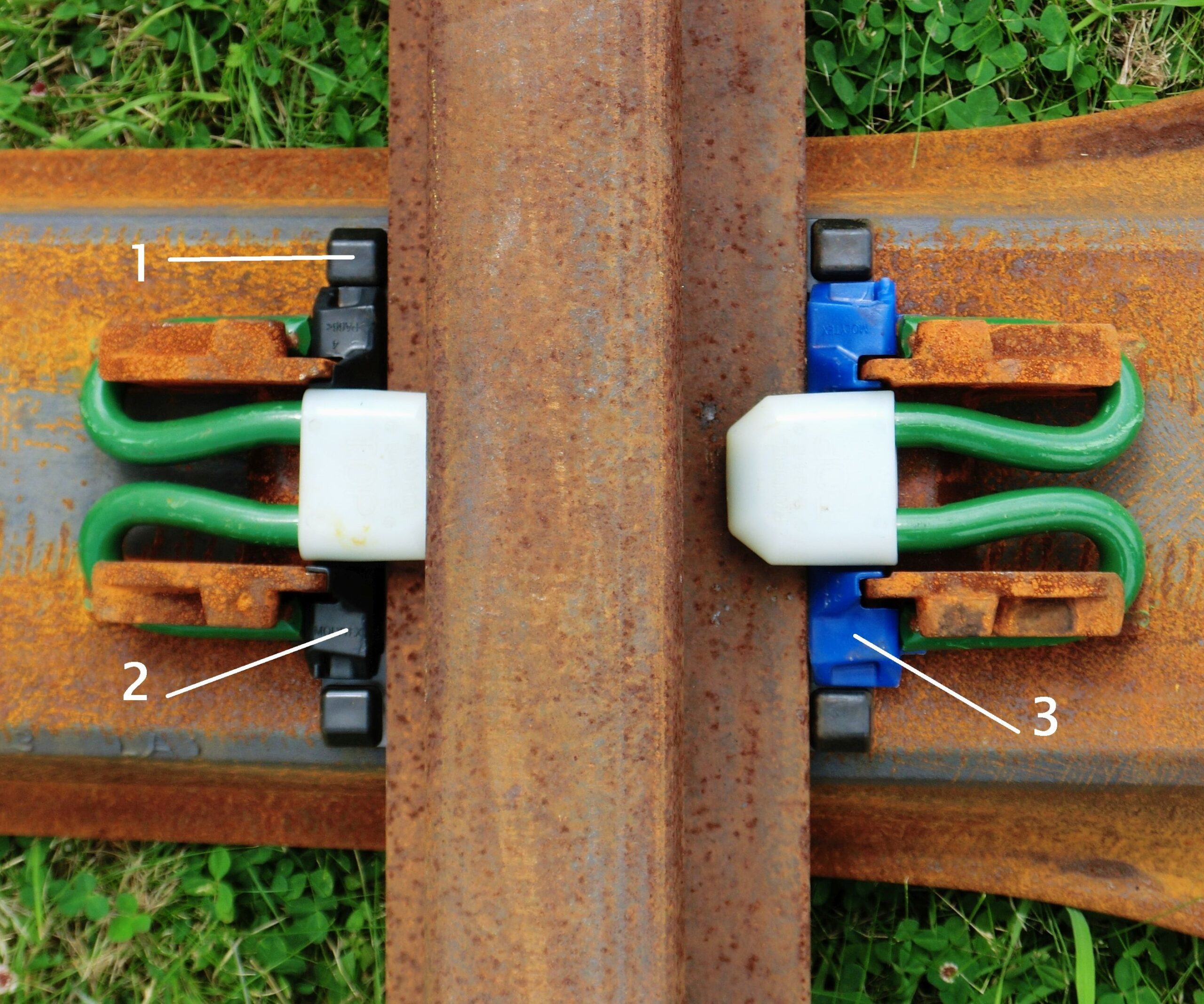
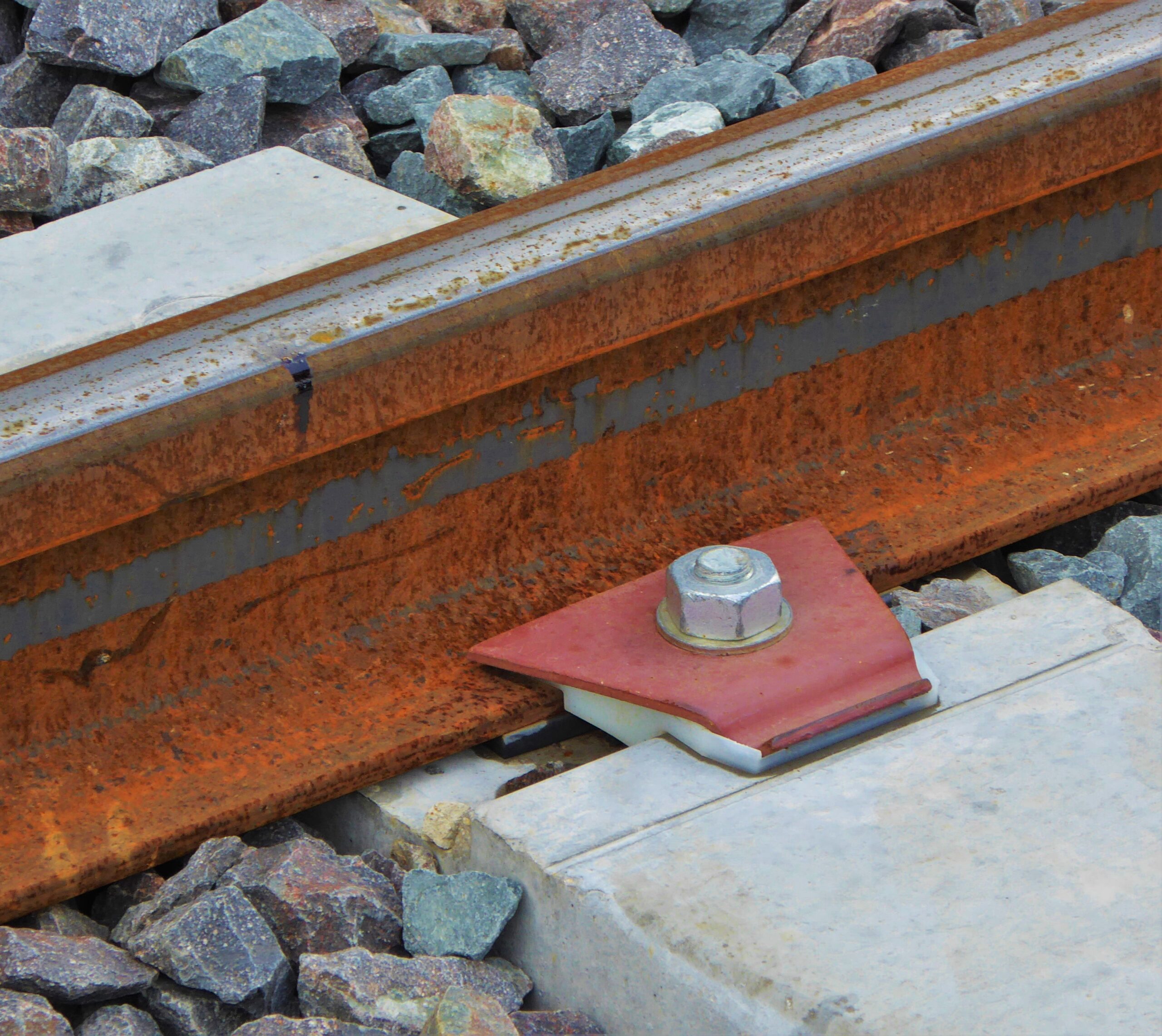
There are many resilient fastenings that incorporate electrical insulation of the rail. The importance of this lies in better functioning of safety current circuits and in limiting stray currents that can cause or aggravate corrosion of metal objects outside the track. Nowadays the rail almost always rests on an (insulating) rail pads – more about this later – and so only the side of the rail foot has to be “done”. This is done with a plastic insulator, which, because it is used in different widths, also allows a small lateral displacement of the rail. This is desirable for the use of different rail foot widths and for the necessary gauge widening in curves.

In the (renovation) construction of railway lines, the center of gravity for the supports has undoubtedly shifted to concrete sleepers. On a very small scale and special applications, there is still some room for plastic sleepers.

Similarly, the situation with rail fastenings has stabilized on three basic types of European manufacturers (Railtech, Pandrol and Vossloh), each of which is used in a large number of variants for the different loads, speeds and rail types that can be distinguished. In addition, there are older models from other suppliers that can survive for various reasons.

The “big three” types are used all over the world, although that is not to say that they are predominant in all countries. In the United States, for example, there is still a lot of spike track and there are also various attachments of American origin in use.


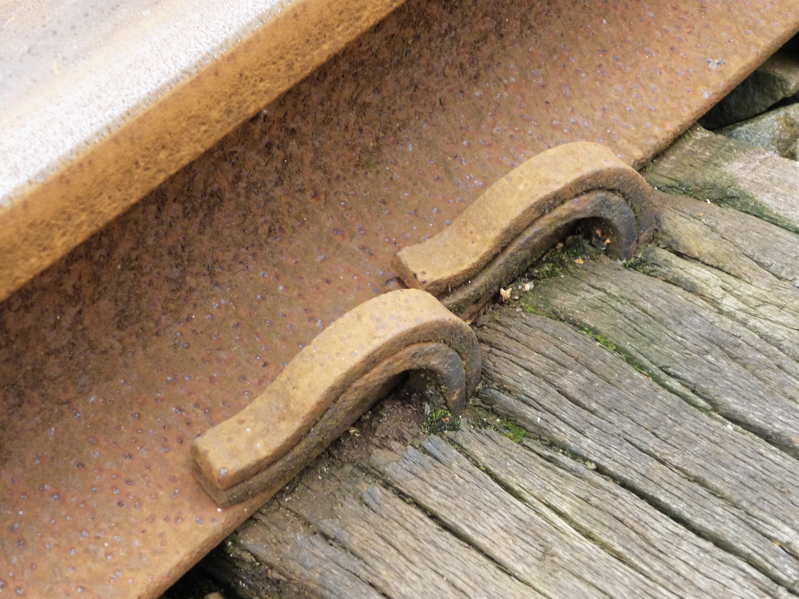
In France, in 1937, Adolphe Guillerot at the French Usine des resorts du Nord de Douai (RN) developed an resilient rail fastening for concrete sleepers called “Crapaud” (seat). Delayed by the Second World War, this confirmation came on the market in 1946. This design was soon developed further in a large context of French organizations, in which the role of each body cannot be properly reconstructed afterwards. In any case, RN, Roger Sonneville for the concrete sleepers, the French state railways SNCF and the engineering bureau Stedef participated. Later there was also a variant “Griffon” for use on wooden sleepers, which were after all still present in large numbers. The last major step in France was the development of the Nabla attachment. In addition, there are plastic parts that combine the functions of electrical insulation and spacer, together with a standard spring steel pressure plate. The commercial affairs for these French designs eventually ended up with the company Railtech, which took over the British-American competitor Pandrol a few years ago and also the name. Since then, Railtech has been called Pandrol France.

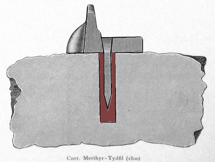
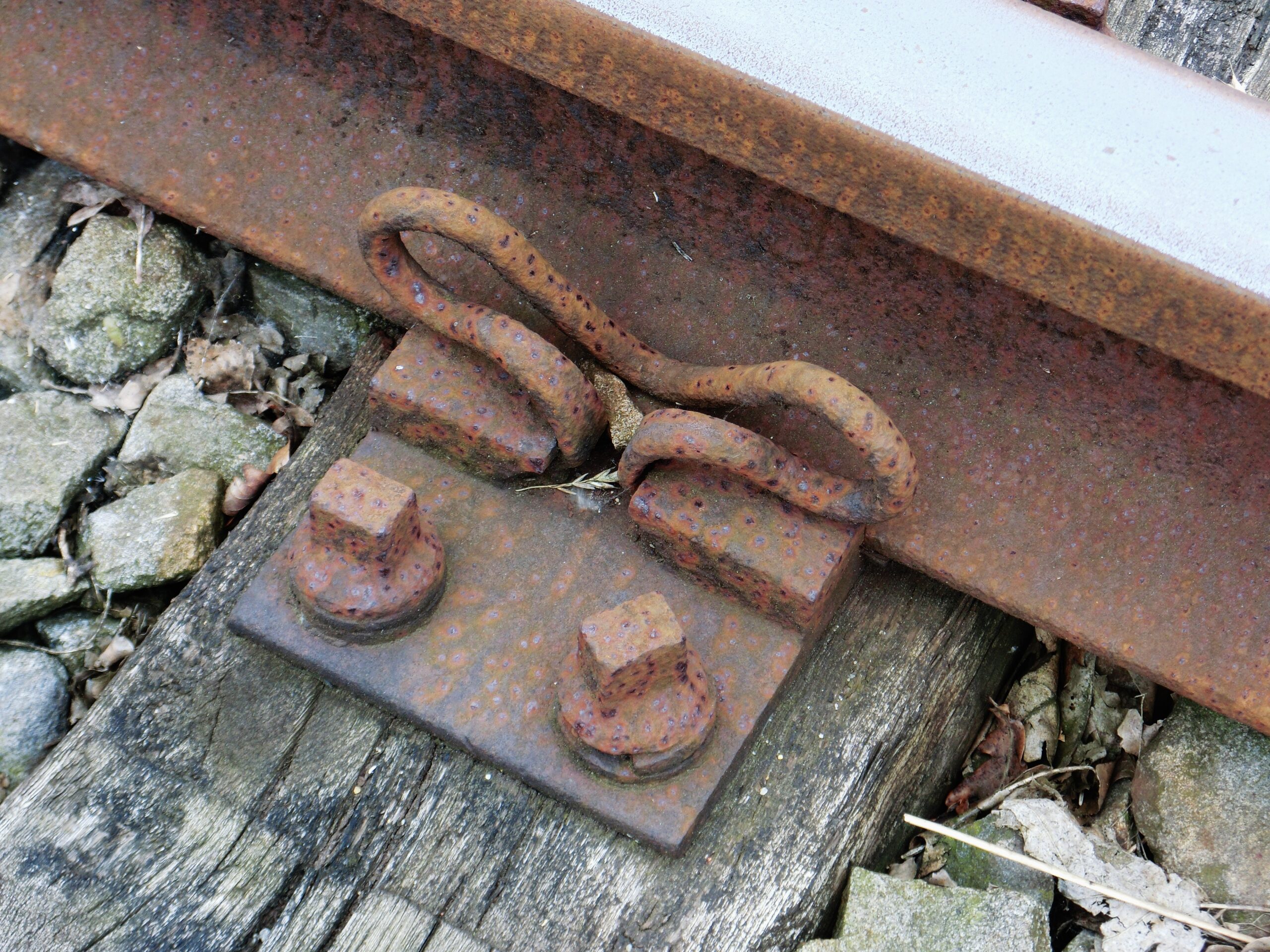
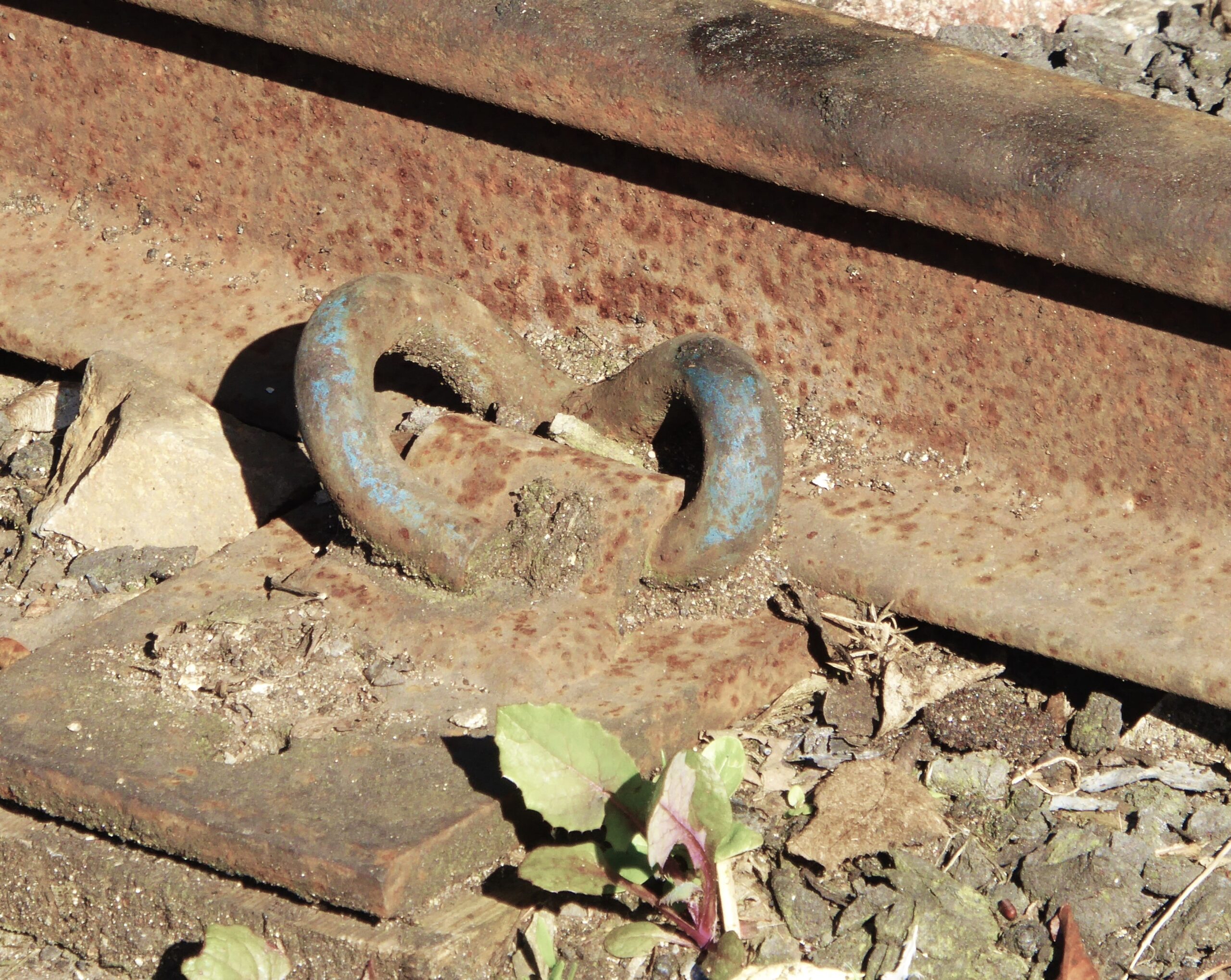
The above-mentioned Elastic Rail Spike was intended for wooden sleepers and one of the two models had the objection that the rail foot rubbed against the spike. At the company, a different concept came within sight because the Norwegian Per Pande-Rolfsen had developed a clip with clip holder in 1957, whereby the rail guide through the holder was so great that the wear was very small and the clamp itself had no wear points. This became the PR clip that could be used on wooden and concrete sleepers with base plates in different shapes and price ranges. The company was renamed after the system’s  success to Pandrol. Clip holders were soon introduced that could be received into concrete sleepers, eliminating much of the field assembly. Despite the very great success of the PR and later the largely comparable e-clips, it remained a disadvantage that the fitting of electrical insulators / spacers and the clips was manual work that had to be carried out on the track and would remain so. This led to the development of the Fastclip, which can be installed and pre-assembled together with all other components in the concrete factory. After the rail has been laid, all you have to do is slide the clips into place mechanically and the track is ready.

In Germany, the Deutsche Bundesbahn (DB) had its own research department in which Hermann Meier played an important role. Later he became independent and continued to develop numerous fastening components and systems. As early as 1949, he obtained patents for series of resilient fasteners, not all of which were successful. That changed when he came up with a forerunner to the HM design named after him in 1965. Because the DB had no manufacturing facilities and did not want them, many of Meier’s inventions for production and sales have been transferred to Vossloh. This company already had a long history as a manufacturer of “Kleineisen” (bolts, washers, spring washers, etc.) for railways.

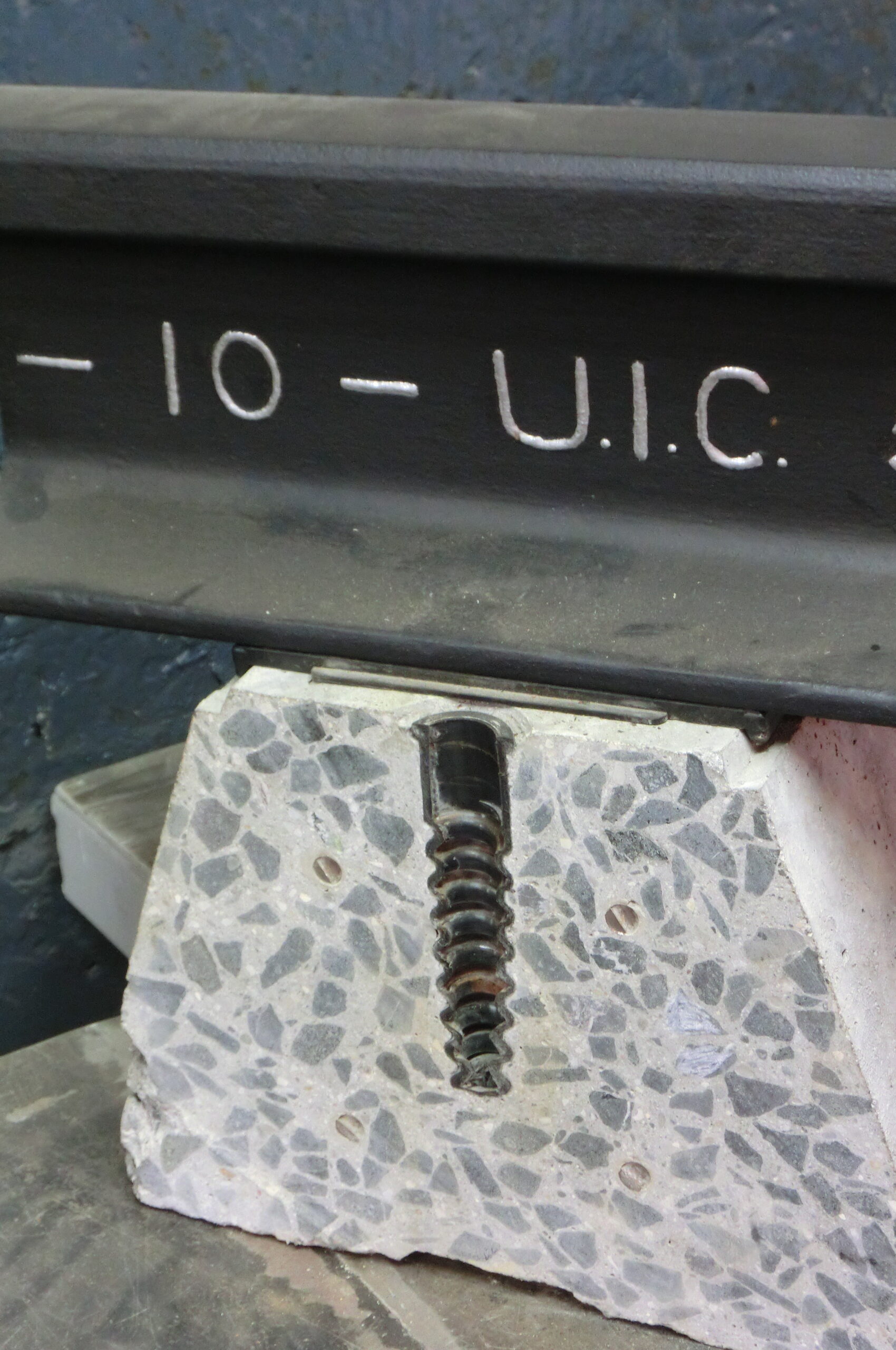
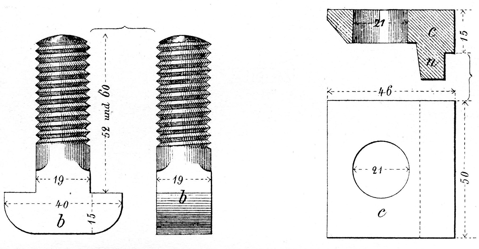
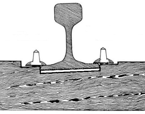
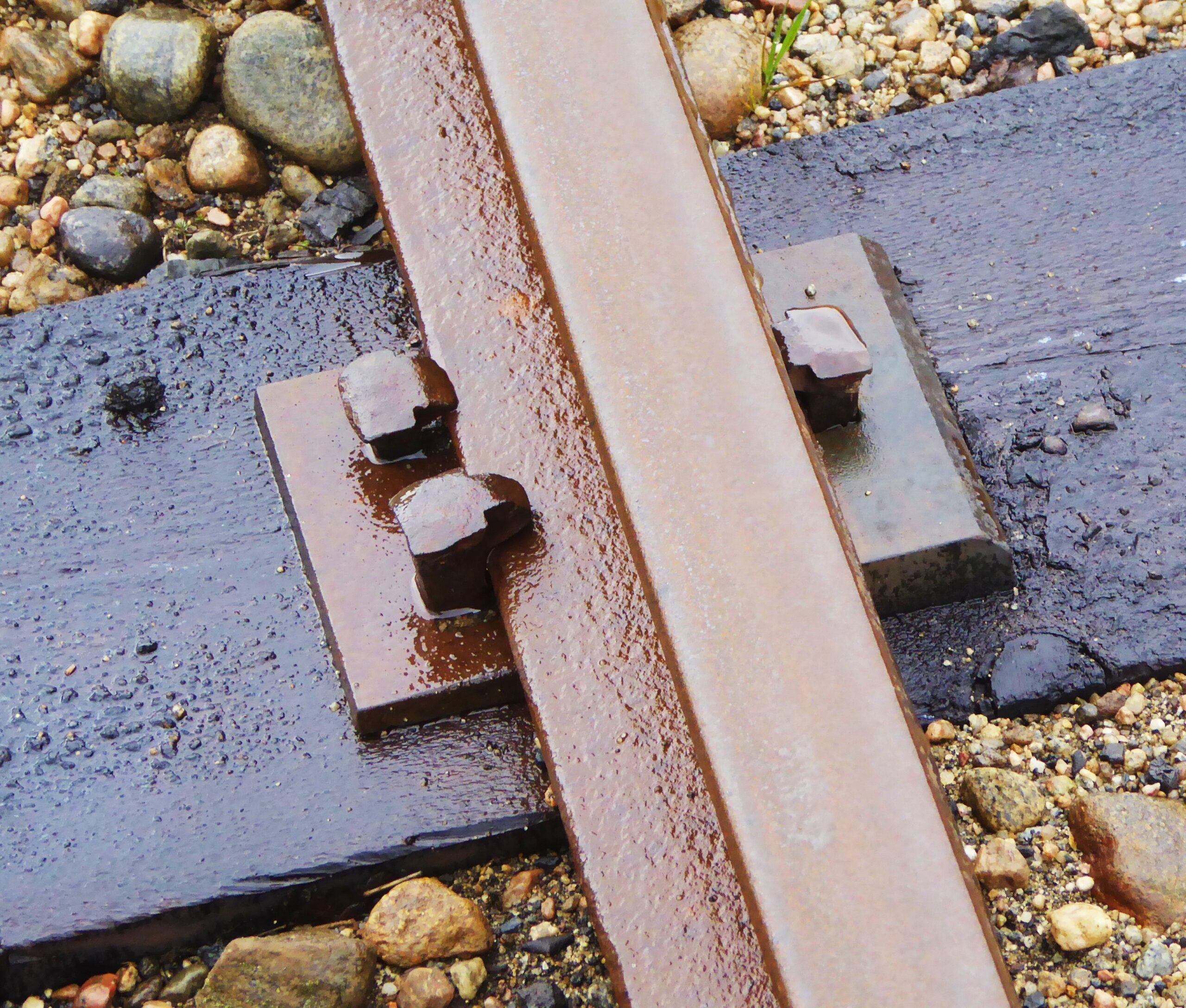
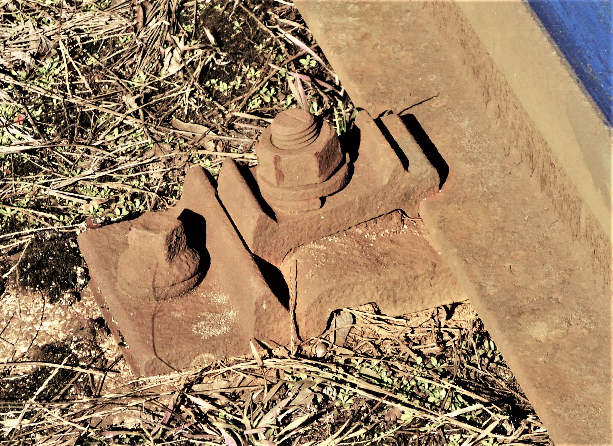
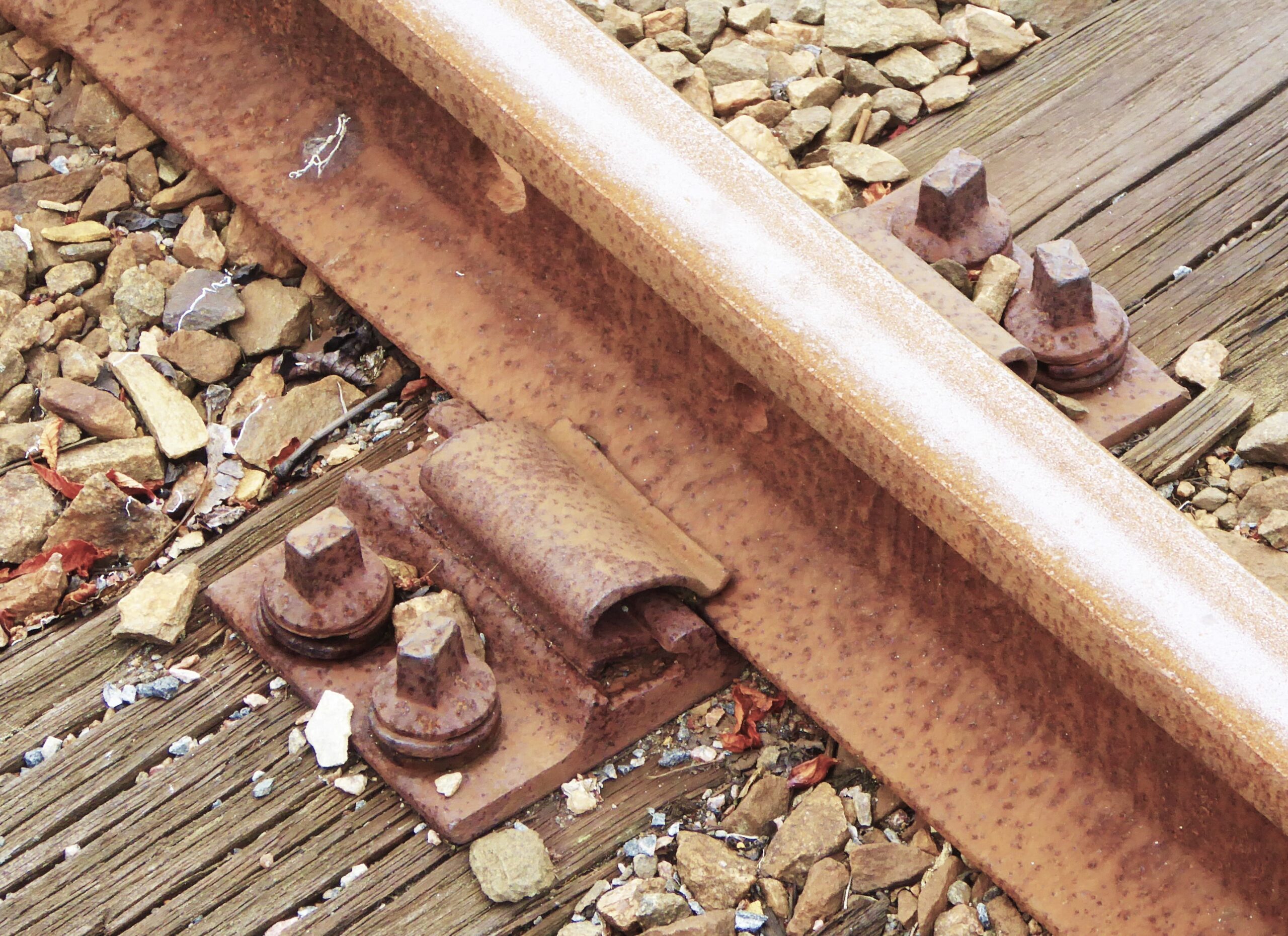
The core of the HM fastening is a ɷ-shaped spring clip that is fixed in the middle with a (collar) bolt and both ends of which press on the rail foot. Variants of this typical spring clip follow different tracks. There are applications to the known K-fastening base plate using a clamping bolt, others with specially developed angled guiding plates and a classic chair screw for use on concrete sleepers, and another using special plastic base plates with chair screws.

The aforementioned “big three” have all protected their inventions against counterfeiting with sometimes very large amounts of patents, but many basic patents have since expired. As a result, more suppliers have now come for “their” systems. In turn, those new suppliers also want to protect what they make improvements. That makes the overview difficult!

In addition to the main components of all those fastening systems, there are countless smaller parts that are indispensable for rail fastenings. It is going too far to list them all here. However, the rail pads and intermediate plates must be mentioned.

Nabla fastening, SNCF Lyon (F), 2017
Pandrol PR-clip, KBWR Brentford (GB), 2018
Vossloh W14 rail fastening Railway museum Vilanova (E), 2014
Embedded track, BRU Smakkelaarsveld Utrecht (NL), 2012

Rail pads and intermediate sheets

The natural rubber plates that were used in the seats of double-headed rail have been much better imitated. It soon became clear that it is good to damp vibrations that occur in train traffic. Not only to protect the track, but also to improve the comfort of travellers and local residents. For a long time, the problem was finding the right material. Natural rubber turned out not to be satisfactory, and resilient plastic did not yet exist. Poplar wood planks were therefore used for the K-mounting. The pads of this soft wood were about 5 to 8 mm thick and are about 2 compressed when a train wheel passes. Due to the slow destruction of the wood fibres of the pads, not only the lifespan is limited, but also the effect. Plastics did much better, of course only when it became available. Various plastics are suitable, such as PVC and neoprene, but cork emulsions are also widely used.

The pads are also used where abrasive wear occurs. It is easy to imagine how a steel rail laid directly on a concrete sleeper will wear down the concrete surface and destroy it in the long run. That has happened on a large scale. The pads that are now used here to lay the rail on must be wear-resistant and therefore of relatively hard plastic. Such pads are also used where steel base plates rest on concrete sleepers.

In places where vibrations have to be dampened very strongly (such as at tunnels and bridges), double damped base plates can be used. In this case, a base plate with a good damping layer is mounted on the support and a second base plate which moves freely in the vertical direction and also has a good damping layer.

The track on concrete slabs (slab track), which is widely used today for train and tram tracks with a high load, has had virtually no influence on the modern rail fastenings. The exception is the embedded track, where the rails are carefully set in gutters and then the gutters filled  with an emulsion. There, in fact, that emulsion has become the rail fastening.